[ Huaqiang Security Network News ] 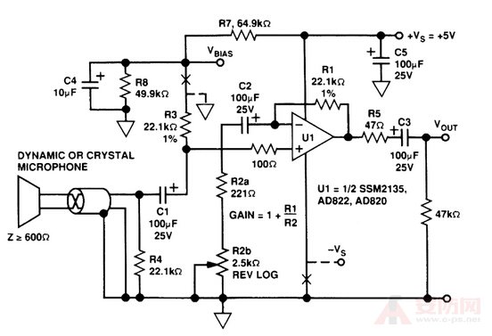
Talking about the audio preamplifier circuit diagram, the A operational amplifier is used as the audio preamplifier circuit. The advantages are small size, low noise, low power consumption and good consistency. Using operational amplifier A, you can achieve deep negative feedback while improving the undistorted output. The signal distortion is below 1%; the amplifier voltage gain can reach 50-80dB.
Among them, cl is a high frequency compensation capacitor, and c2 and R2 are decoupling filter circuits. Adjusting the potentiometer RPl balances the common mode rejection ratio. Potentiometer RP2 is a negative feedback component. Adjusting the RP2 changes the output level.
Component selection: Capacitance cl is 82P, c2 is 100p/25v. The resistor R1 is 27kn, R2 is 100n, and R3 is 50kn. Potentiometer RPl10kn, RP2 is 100kn. The integrated operational amplifier A uses GF2A. Transformer T is replaced by a small output transformer commonly used in crystal tube radios.
Vacuum Cleaner Tube,Vacuum Cleaner Hose,Vacuum Cleaner Pipe,Bulk Vacuum Cleaner Hose
Changxing VACUFLEX Hose Technology Co., Ltd. , https://www.vacuflex-cn.com