1. Introduction to STM32 mer
There are 11 timers in STM32, including 2 advanced control timers, 4 normal timers and 2 basic timers, as well as 2 watchdog timers and 1 system timer. The system 嘀嗒 timer is the Sysck described in the previous section, and the watchdog timer will be studied in detail later. Today is mainly to study the remaining 8 timers.
| Timer | Counter resolution | Counter type | Prescaler coefficient | Generate DMA request | Capture/compare channel | Complementary output |
| M1 M8 | 16 bits | Up, down, up/down | Any number between 1-65536 | can | 4 | Have |
| TIM2 TIM3 TIM4 TIM5 | 16 bits | Up, down, up/down | Any number between 1-65536 | can | 4 | No |
| TIM6 TIM7 | 16 bits | up | Any number between 1-65536 | can | 0 | No |
Among them, TIM1 and TIM8 are advanced timings capable of generating three pairs of PWM complementary outputs, which are commonly used for driving three-phase motors, and the clock is generated by the output of APB2. TIM2-TIM5 is a normal timer, TIM6 and TIM7 are basic timers whose clock is generated by the APB1 output. Since the TITM function of STM32 is too complicated, it can only be learned a little bit. So today, from the simplest to learn, that is, the timing function of the TIM2-TIM5 ordinary timer.
2 basic timer TIM6-TIM7
2.1 Basic characteristics of the clock
The basic timers TIM6 and TIM7 each contain a 16-bit autoload counter that is driven by its respective programmable prescaler. They provide a time reference as a general-purpose timer, specifically clocking digital-to-analog converters (DACs). In fact, they are directly connected to the DAC inside the chip and directly drive the DAC through the trigger output. These two timers are independent of each other and do not share any resources.
2.2 Main features of TIM6-7
The main features of the TIM6 and TIM7 timers include:
â— 16-bit auto-reload accumulator counter
â— 16-bit programmable (real-time modification) prescaler for any value between 1 and 65536 for the input clock
Frequency division
â— Synchronous circuit that triggers the DAC
â— Generate interrupt/DMA request during update event (counter overflow)
Figure 144 Basic timer block diagram
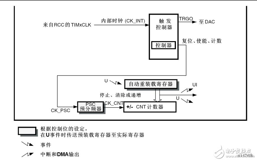
2.3 Counter mode
The TIM6-TIM7 can be counted up. In the up counting mode, the counter counts from 0 to the autoload value (TIMx_ARR counter contents), then restarts counting from 0 and generates a counter overflow event.
2.4 Register of TIM6-TIM7 Basic Timer
1.TIM6 and TIM7 Control Register 1 (TIMx_CR1)
ARPE: Auto-reload preload enable 0: TIMx_ARR register is not buffered 1: TIMx_ARR register has buffer
URS: Update request source
This bit is set and cleared by the software to select the request source for the UEV event.
0: If an interrupt or DMA is enabled, any of the following events can generate an update interrupt or DMA request:
- Counter overflow or underflow
- Set the UG bit
- via updates generated from the mode controller
1: If an interrupt or DMA is enabled, only the counter overflow or underflow can generate an update interrupt or a DMA request.
UDIS: Update disabled (Update disable)
This bit is set and cleared by software to enable or disable the generation of UEV events.
0: UEV is enabled. Update events (UEV) can be generated by the following events:
- Counter overflow or underflow
- Set the UG bit
- via updates generated from the mode controller
After the update event is generated, the buffered registers are loaded as preloaded values.
1 : UEV is prohibited. The update event (UEV) is not generated and the shadow register holds its contents (ARR, PSC). But if set
The UG bit or a hardware reset generated from the mode controller will re-initialize the counter and prescaler.
CEN: Counter enable (Counter enable)
0: Turn off the counter
1: enable counter
2.TIM6 and TIM7 Control Register 2 (TIMx_CR2)
3. TIM6 and TIM7 DMA/Interrupt Enable Register (TIMx_DIER)
UDE: Update DMA request enable
0: Disable update of DMA request
1: Enable update DMA request
UIE: Update Interrupt Enable
0: Disable update interrupt
1: Enable update interrupt
4 . TIM6 and TIM7 status registers (TIMx_SR)
UIF: Update interrupt flag The hardware sets this bit when updating interrupts, which is cleared by software.
0: No update was generated.
1: An update interrupt has been generated. This bit is set by hardware in the following cases:
– the counter generates an overflow or underflow and UDIS=0 in TIMx_CR1;
– If URS=0 and UDIS=0 in TIMx_CR1, when the counter CNT is reinitialized using the UG bit of the TIMx_EGR register.
5. TIM6 and TIM7 event generation registers (TIMx_EGR)
UG: Generate update event (Update generation) This bit is set by the software and is automatically cleared by hardware.
0: no effect
1 : Re-initialize the counter of the timer and generate an update to the register. Note: The prescaler is also cleared (but the prescaler coefficients are unchanged).
6. TIM6 and TIM7 counters (TIMx_CNT)
CNT[15:0]: Counter value (Counter value)
7. TIM6 and TIM7 prescaler (TIMx_PSC)
PSC[15:0] : Prescaler value The counter clock frequency CK_CNT is equal to f CK_PSC/(PSC[15:0]+1).
At each update event, the value of the PSC is transferred to the actual prescaler register.
8. TIM6 and TIM7 auto-reload registers (TIMx_ARR)
ARR[15:0] : Prescaler value The value of ARR is transferred to the actual auto-reload register.
If the auto-reload value is 0, the counter stops.
2.5 Programming steps
1. Configure the priority;
2. Enable the clock
3. Configure GPIO;
4. Configure TIME;
5. Enable the counter;
6. Open the interrupt;
7. Clear the flag bit;
The specific configuration is as follows:
(1) NVIC_Configuration(void); configuration priority
(2) void RCC_APB2PeriphClockCmd(uint32_t RCC_APB2Periph, FunctionalState NewState) Enable clock
(3) void GPIO_Init(GPIO_TypeDef* GPIOx, GPIO_InitTypeDef* GPIO_InitStruct); configure GPIO
(4) TIM_Configuration (void); configure TIM6/TIM7
(5) TIM_Cmd (TIM7, ENABLE); enable timer
(6) TIM_ITConfig (TIM7, TIM_IT_Update, ENABLE); enable interrupt
(7) TIM_ClearFlag (TIM7, TIM_FLAG_Update); clear flag
The prescaler coefficient in step (4) is used to determine the clock frequency used by the TIMx. The specific calculation method is: CK_INT/(TIM_Perscaler+1). CK_INT is the frequency of the internal clock source, which is the clock sent by the multiplier of APB1 described in 2.1. TIM_Perscaler is the user-set prescaler coefficient, and its value ranges from 0 – 65535.
The clock division in step (4) defines the timer clock frequency (CK_INT) and the digital filter.
(ETR, TIx) The division ratio between the sampling frequencies used. The parameters of TIM_ClockDivision are as follows:
| TIM_ClockDivision | description | Binary value |
| TIM_CKD_DIV1 | tDTS = Tck_tim | 0x00 |
| TIM_CKD_DIV2 | tDTS = 2 * Tck_tim | 0x01 |
| TIM_CKD_DIV4 | tDTS = 4 * Tck_tim | 0x10 |
It is necessary to prohibit the use of the preload buffer in step (4). When the preload buffer is disabled, the value written to the autoloaded value (TIMx_ARR) is passed directly to the corresponding shadow register; if the preload register is enabled, the value written to the ARR will be updated when the event occurs. It will be transferred from the preload register to the corresponding shadow register.
In ARM, some logical registers physically correspond to two registers, one is a register that the programmer can write or read, called a preload register, and the other is invisible to the programmer, but in The register that actually works in the operation is called the shadow register. The advantage of designing the preload register and the shadow register is that all the shadow registers that really need to be active can be used at the same time (when an update event occurs). Updated to the content of the corresponding preload register, which ensures that the operation of multiple channels can be accurately synchronized. If there is no shadow register, or if the preload register and shadow register are pass-through, that is, when the software updates the preload register, the shadow register is updated at the same time, because the software cannot update multiple registers at the same time at the same time, resulting in timing of multiple channels. Cannot synchronize, if other factors (such as interrupts) are added, the timing relationship of multiple channels may be unpredictable.
3. Program source code
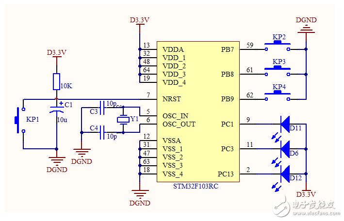
In this example, the timing function of the TIM7 is used to make the LEDs flash at intervals of 1 s.
Schematic:
/*
* File name: main.c
* Description of content:
* Create a project from 0, trigger the interrupt 1 by button 1 to achieve the flashing of the lamp 1
* Then trigger interrupt interrupt preemption 1 by button 2 to realize the flashing of small light 2
*
* 2 LED indicators, the corresponding GPIO is: PC3 PC1
* Output is 0 to light the LED
* Output is 1 to turn off the LED
* 2 buttons for PB7 PA11
*/
#include "stm32f10x.h"
/* delay function */
Void Delay(__IO uint32_t nCount)
{
//__IO is volatile, plus this can prevent the delay function from being optimized by the compiler.
For(;nCount != 0; nCount--);
}
/* GPIO configuration function */
Void GPIO_Configuration(void)
{
/* defines 2 structure variables */
GPIO_InitTypeDef GPIO_InitStructure;
/*Enable GPIOB, GPIOC, multiplexer clock clock*/
RCC_APB2PeriphClockCmd(RCC_APB2Periph_GPIOC, ENABLE);
RCC_APB1PeriphClockCmd(RCC_APB1Periph_TIM7, ENABLE);
/* Give GPIO_InitStructure.GPIO_Pin GPIO_InitStructure.GPIO_Mode GPIO_InitStructure.GPIO_Speed ​​Pay initial value*/
GPIO_InitStructure.GPIO_Pin = GPIO_Pin_3;
// Set the GPIO connected to LED3 to push-pull output
GPIO_InitStructure.GPIO_Mode = GPIO_Mode_Out_PP;
/ / set to 10MHZ speed
GPIO_InitStructure.GPIO_Speed ​​= GPIO_Speed_50MHz;
/ / Initialize GPIOC
GPIO_Init(GPIOC, &GPIO_InitStructure);
}
/********Configure priority *****************/
Void NVIC_Configuration(void)
{
/ / Define a structure
NVIC_InitTypeDef NVIC_InitStructure;
/ / Set the priority group
NVIC_PriorityGroupConfig(NVIC_PriorityGroup_0) ;
/ / Set the TIM7 line
NVIC_InitStructure.NVIC_IRQChannel =TIM7_IRQn;
/ / Enable priority
NVIC_InitStructure.NVIC_IRQChannelCmd = ENABLE;
/ / Configure stealing priority
NVIC_InitStructure.NVIC_IRQChannelPreemptionPriority =0;
/ / Configure response priority
NVIC_InitStructure.NVIC_IRQChannelSubPriority =0;
NVIC_Init(&NVIC_InitStructure);
/ / Set the deposit register
NVIC_SetVectorTable (NVIC_VectTab_FLASH, 0x0);
}
//***** Timer initialization *********
Void TIM_Configuration (void)
{
TIM_TimeBaseInitTypeDef TIM_TimeBaseStructure;
// TIM_Cmd(TIM7, DISABLE);
//The prescaler coefficient is 36000-1, so the counter clock is 72MHz/36000 = 2kHz
TIM_TimeBaseStructure.TIM_Prescaler = 36000 - 1;
/ / Set the clock split TIM_CKD_DIV1 = 0x0000, not split
TIM_TimeBaseStructure.TIM_ClockDivision = 0;
/ / Set the counter mode to count up mode
TIM_TimeBaseStructure.TIM_CounterMode = TIM_CounterMode_Up ;
/ / Set the count overflow size, an update event is generated every 2000 counts
TIM_TimeBaseStructure.TIM_Period = 2000 - 1;
TIM_TimeBaseStructure.TIM_RepetitionCounter = 0;
/ / Apply the configuration to TIM7
TIM_TimeBaseInit(TIM7,&TIM_TimeBaseStructure);
TIM_UpdateRequestConfig( TIM7, TIM_UpdateSource_Regular);
/ / Enable the counter
TIM_Cmd(TIM7, ENABLE);
/ / Enable interrupt
TIM_ITConfig(TIM7, TIM_IT_Update, ENABLE);
/ / Clear flag
// TIM_ClearFlag(TIM7, TIM_FLAG_Update);
}
//*****************************
/ / Main function
Int main(void)
{
/*
This function is a function in the ST library, the function entity is
Libraries\CMSIS\Core\CM3\system_stm32f10x.c
Configure the internal Flash interface, initialize the PLL, and configure the system clock frequency.
The system clock is configured by default to 72MHz.
*/
GPIO_Configuration ();
NVIC_Configuration ();
TIM_Configuration ();
While(1)
{
}
}
Program in it.c
Void TIM7_IRQHandler(void)
{
/ / Check if an overflow update event occurs
If(TIM_GetITStatus(TIM7, TIM_IT_Update)== SET)
{
GPIOC-"ODR ^= GPIO_Pin_3;
TIM_ClearITPendingBit(TIM7, TIM_FLAG_Update);
}
}
Programming experience:
1. Note that the application timer is to enable TIM_Cmd (TIM7, ENABLE) - counter enable TIM_ITConfig (TIM7, TIM_IT_Update, ENABLE) - interrupt enable RCC_APB1PeriphClockCmd (RCC_APB1Periph_TIM7, ENABLE) - clock
2. Be sure to remember the flag bit TIM_ClearITPendingBit (TIM7, TIM_FLAG_Update) after entering the interrupt;
Stainless Steel Utentials For Hospital
Hospital Trolley Cart,Hospital Drug Trolley,Hospital Notes Trolley,Hospital Equipment Trolley
Xinhe Stainless Steel Products Co., Ltd. Of Pengjiang District Jiangmen City , https://www.sinkhall.com